It has been quite a while since the last post and the reason is that I just could not get two chips working on the same SPI bus until now. I had the basics right but a few different things were missed causing me issues. The good news is along the way I learned how to use a new tool.
Adding the second potentiometer to the example should have been easy. The hookups are all basically the same with the exception of the chip select and voltage sense line for the second chip. The chip select had to be different so that each chip knew which one should be listening to the SPI bus and the voltage sense so that we can read the state of each chips output. The updated software looks like:
#include <SPI.h>
const int CS = 10;
const int CS2 = 9;
int PotWiperVoltage = A0;
int PotWiperVoltage2 = A1;
int RawVoltage = 0;
int RawVoltage2 = 0;
float Voltage = 0;
float Voltage2 = 0;
void setup() {
pinMode (CS, OUTPUT);
pinMode (CS2, OUTPUT);
digitalWrite(CS, HIGH);
digitalWrite(CS2, HIGH);
Serial.begin(9600);
SPI.begin();
SPI.setClockDivider(SPI_CLOCK_DIV128);
}
void loop() {
for (int level = 255; level > 0; level–)
{
MCP41010Write(level, CS2);
delay(100);
MCP41010Write(254-level, CS);
delay(100);
RawVoltage = analogRead(PotWiperVoltage);
Voltage = (RawVoltage * 5.0 ) / 1024.0;
Serial.print(“Level = ” );
Serial.print(level);
Serial.print(“\t Voltage = “);
Serial.println(Voltage, 3);
RawVoltage2 = analogRead(PotWiperVoltage2);
Voltage2 = (RawVoltage2 * 5.0 ) / 1024.0;
Serial.print(“Level2 = ” );
Serial.print(255-level);
Serial.print(“\t Voltage2 = “);
Serial.println(Voltage2, 3);
delay(100);
}
delay(2000);
}
void MCP41010Write(byte value, int p)
{ // Note that the integer vale passed to this subroutine
// is cast to a byte
digitalWrite(p, LOW);
SPI.transfer(B00010001); // This tells the chip to set the pot
SPI.transfer(value); // This tells it the pot position
digitalWrite(p, HIGH);
}
That is all well and good, but here are where things went wrong. For my first test I had the USB Host Shield in place on my arduino because it will be in place when I build the full project. The behavior I was seeing is that one chip, the one with CS on pin 10 of the arduino, worked as expected with the voltage changing, but the one with the CS on pin 9 had its output frozen at an arbitrary voltage in the middle of the range. Some of you in the audience may already raising your hands to tell me what I had done wrong. Don’t worry we will get there.
This is where the first delay in this work came in because I needed to see what was happening on the SPI bus, it seemed like the chip select line for one chip was dead but there was no reason, that I knew of at the time anyway, for the pin to not be operating. I ordered myself a cheap usb logic analyzer.
That started the next adventure, I needed to learn how to use this new device and just hooking it up to this project was showing me data I could not yet interpret. I decided to get simple and learn so I created a sketch that would toggle two of the digital pins of an arduino once a second with one pin high and the other low at any one time. I switched to a seeduino cortex m0+ for this because it was handy and I would like to use this in my final project and didn’t want to deal with possible bad pins on the arduino that had the USB host shield on it. Then I hooked up a regular multimeter in voltage read mode just to check that the values where toggling as expected. Next I hooked up the logic analyzer with each pin connected to a channel and ran a trace. It was a success, I could see a trace of each pin doing as expected.
Next I hooked the digital pot chips back up, this time to the seeduino because it was out, and tried the test software again. The logic analyzer showed that the chip select lines were working but I couldn’t see any data or clock signals. Also neither of the digital pots were changing, they were frozen at an arbitrary voltage. Something was wrong.
Finally, after letting the project ferment on the bench for a while, I decided to pull out yet another arduino, an uno again this time, and wire everything back up. Much to my surprise, after double checking and fixing a miswiring, everything worked. I was even able to catch a nice logic analyzer trace after I slowed down the SPI clock.
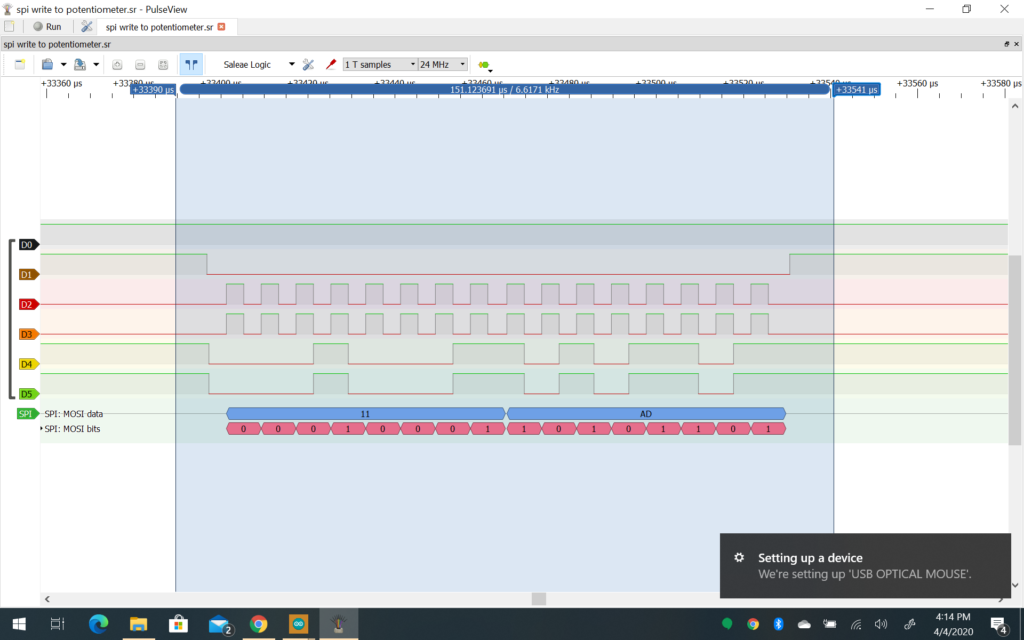
So what have I learned from this process, other than the original goal of getting two digital potentiometers to work together. First I learned that the USB host shield uses pin 10 for chip select, and pins 7, 8, and 9 for other purposes which is why the chip connected to pin 10 for chip select worked and the other one did not. Second I learned that the spi library code for the seeduino is not working. It even gives an error in the IDE saying it might not be compatible so I’ll have to circle back in the future and see if I can resolve that as I’d really like to use this board to drive my project. Lastly I learned how to use my logic analyzer including the fact that 24mhz really much resolution when dealing with SPI that is running at 4mhz. I think I could have zoomed enough to see the data on the bus but it was much easier just slowing down the SPI clock to catch the trace. More to explore in the future.
Next steps for the project are to switch to the MCP4251-104E/P which is a dual pot 100k ohm version of the MCP401010-E/P as it makes the wiring easier. At that point I’ll connect up the DIN-6 breakout board to the project so I can plug in the coco and see if I can actually read the “joystick” using coco basic.